I am delivering this part of the homework a couple of minutes late(update: I finished in 5.29 AM 😀) because I was dealing with some artifacts in my resulting images. This has caused me to panic a little so I’m taking a deep breath and going to explain the difficulties I’ve encountered and how I solved them. I used to get very poor results in lab exams even if I knew the subject due to panicking when I was younger. This instinct still kicks in today sometimes so I have to work on it and be more cold blooded 😀
So, I would like to explain what we have done in this part. For this part of our projects, we have implemented;
- Advanced Lighting
- Spot Lights
- Environment Lights
- Directional Lights
- Area Lights (We had already implemented it)
And secondly, we have also implemented hdr imaging and tonemapping and of course ability to read and write .exr files as well.
I want to make this project as portable as possible so I tried to use header only libraries only. I’m using tinyexr for reading and writing .exr files and I think it does the job.
I tried the project on my workstation(windows MinGW) at work and my ubuntu pc at home and cmake does its job nicely.
Refactoring Lights
When I first started this project, I was trying to implement a raytracer which runs on GPU with OpenGL compute shaders. However, after a while, I got stuck and decided to start over without OpenGL. I was avoiding OOP as much as I could so because of that, my code became a lot messier.
Since we are adding new light types to our raytracer, I guess that is the right time for a refactoring on my light implementation. I created a base Light class and all the lights (Point, Spot, Environment, Area, Directional) are children of this class.
After cleaning the code, I moved on implementing Advanced Lighting
Directional Lights
It was relatively easy to implement this. There is only one direction that the light is coming and the rest is just usual shading. Here is the result I got;
I have learnt that directional lights are used for modeling light sources which are far away from the scene and have very high intensity (like the sun)
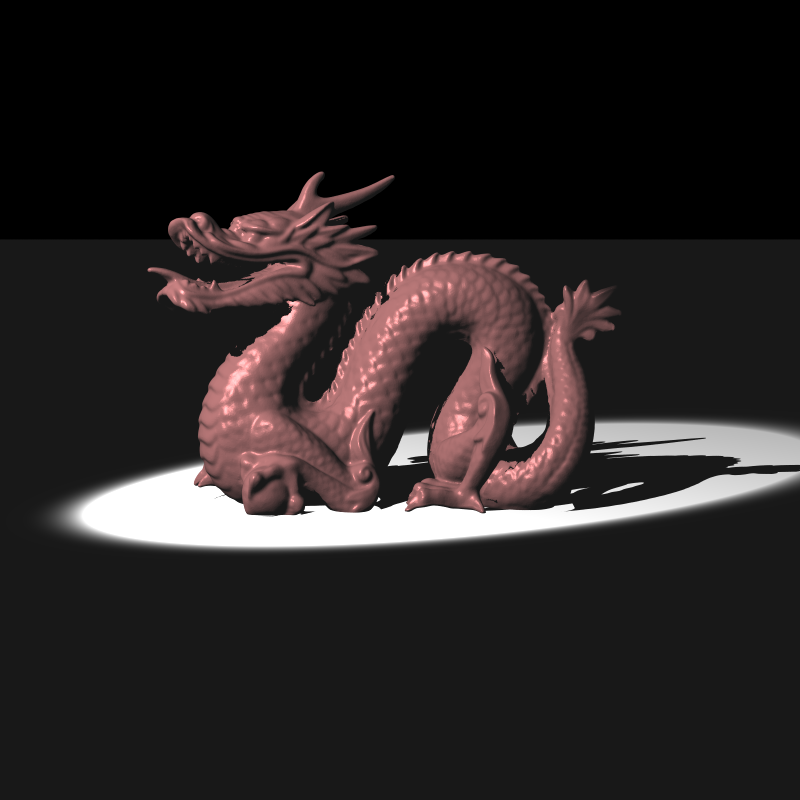
Spot Lights
Spot lights are really cool. I guess those flashlights we use especially in horror games are just spot lights and the logic behind it is the same. It behaves like a point light, but there are two angles called coverage angle and falloff angle.
We get the normalized direction from spot light position to the intersection point that we are testing and check the angle between this direction and the direction of the spot light. By looking at this angle, we can determine whether this point gets full or reduced intensity or nothing at all if it is completely out of spot lights area. Here is my result;
Environment and Area Lights
Before explaining Environment lights in detail, I want to talk about hdr imaging because they are related. Secondly, we had already implemented Area Lights earlier so that was my result;
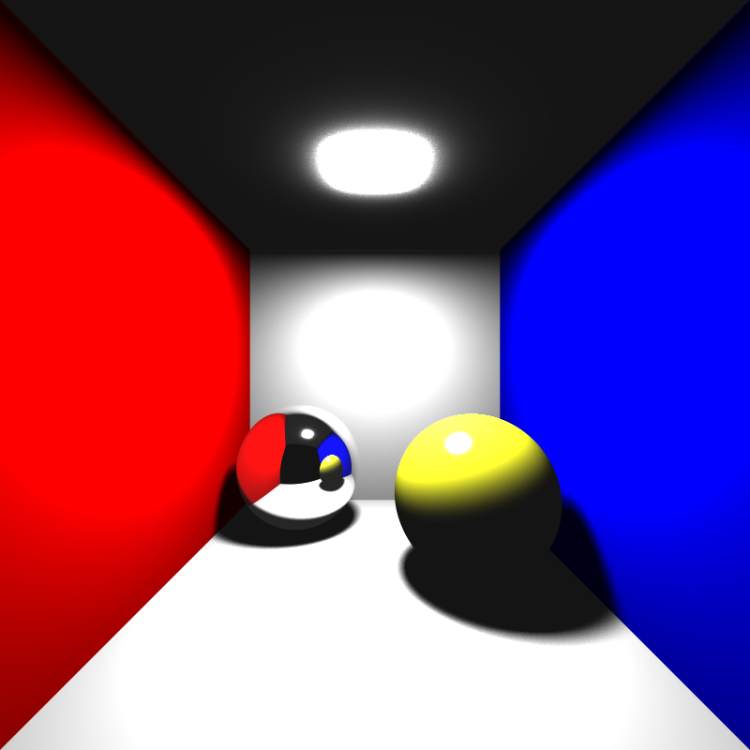
For this part, I can say that both area lights and environment lights use random sampling.
Here is my environment light result;
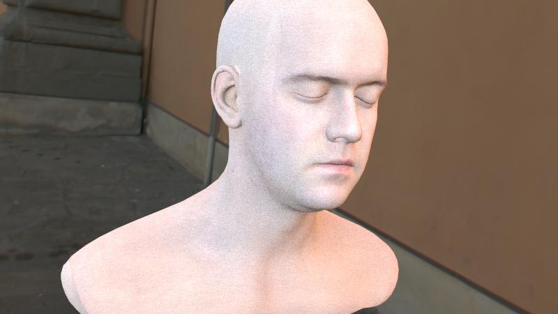
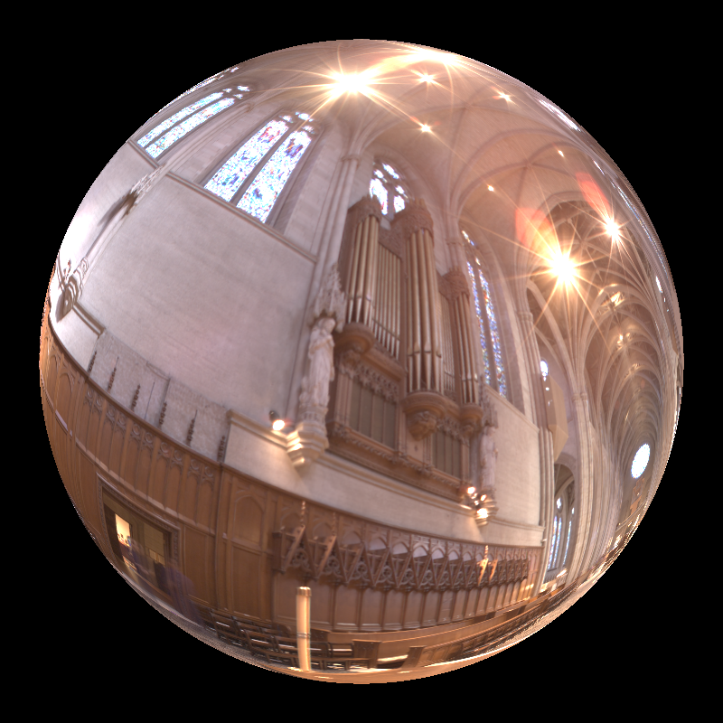
In this part, we are reading an hdr image and using it as the light source. Each pixel value in this image represents intensity coming from that pixel. In order to get light from this image what we do is;
- Randomly select a vector which has positive dot product with the surface normal and its norm is less then or equal to 1
- Use this vector with our main coordinate frame which is;
- u (1,0,0)
- v (0,1,0)
- w(0,0,1)
- And find u,v coordinates from the angles (theta and phi) this vector makes with and get the u,v values to fetch from our hdr image just like we did in texture mapping to spheres.
HDR Imaging
I don’t know why but I struggled a lot here. I was getting similar outputs they were far from correct in my opinion. I am going to explain the mistakes I managed to identify and correct. But first, I would like to explain what I’ve understood from photographic tone mapping.
I’ve implemented Reinhard’s global tone mapping approach. First of all, I needed to understand how to find luminance of an RGB pixel. It turns out that the luminance of a pixel is;
L = R*0.27 + G*0.67 + B*0.06In class we have learnt that human visual system is much more sensitive to green light and least sensitive is blue light. I think the equation above satisfies this. I tried to correctly implement but I think that I made some mistakes because everything is not clear in my mind right now. But I want to explain what I’ve understood from it with pseudo codes.
So, I guess for each pixel we have to calculate its luminance and get an average luminance by processing each pixel like this;
float av_lum = 0;
for(auto pixel : pixels)
{
    float lum = pixel.r * 0.27 + pixel.g * 0.67 + pixel.b * 0.06;
    av_lum += std::log(0.000005 + lum);
}
av_lum = std::pow(EULER, av_lum/(ImageWidth*ImageHeight));
We also need to map the log average. We do it like this
lm = (a * lum_pixel)/(av_lum)We may select different a’s for mapping to different(grayscale) zones in the image.
And then, we have to find a threshold luminance. What I mean is, a pixel with equal or higher luminance then threshold will be pure white. I think this is the thing which they call “burn”. Then I tried to understand how can I get this threshold value and came up with an idea;
Normally, paper says that this threshold is the maximum luminance in the image. So in that case, we have a sigmoid function. Which means that the function converges to 1
Then, we use this value from sigmoid function on pixels, gamma correct and scale the result by 255. It is not completely clear for me but with this approach, I’m getting very similar results. For example;
Here, I’m taking the threshold value as the average luminance and multiplying it with the burn_percentage(this might be a wrong approach I don’t know).
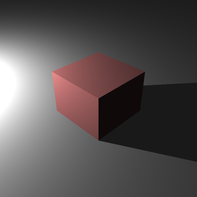
Another example is
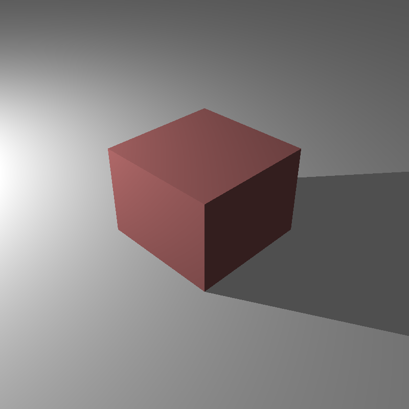
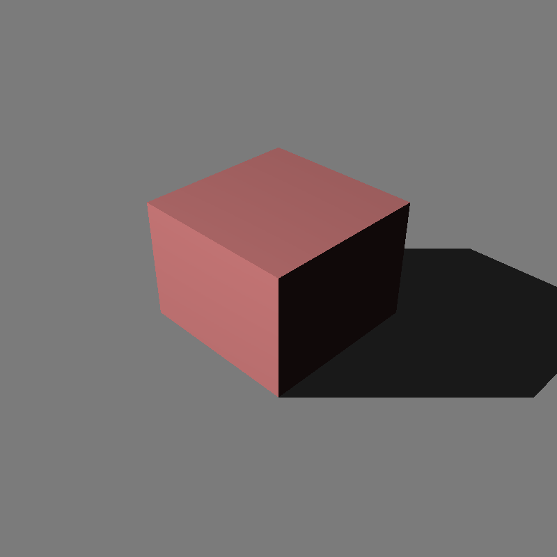
I have spent maybe 4 or 5 hours trying to get the image above. I was getting this;
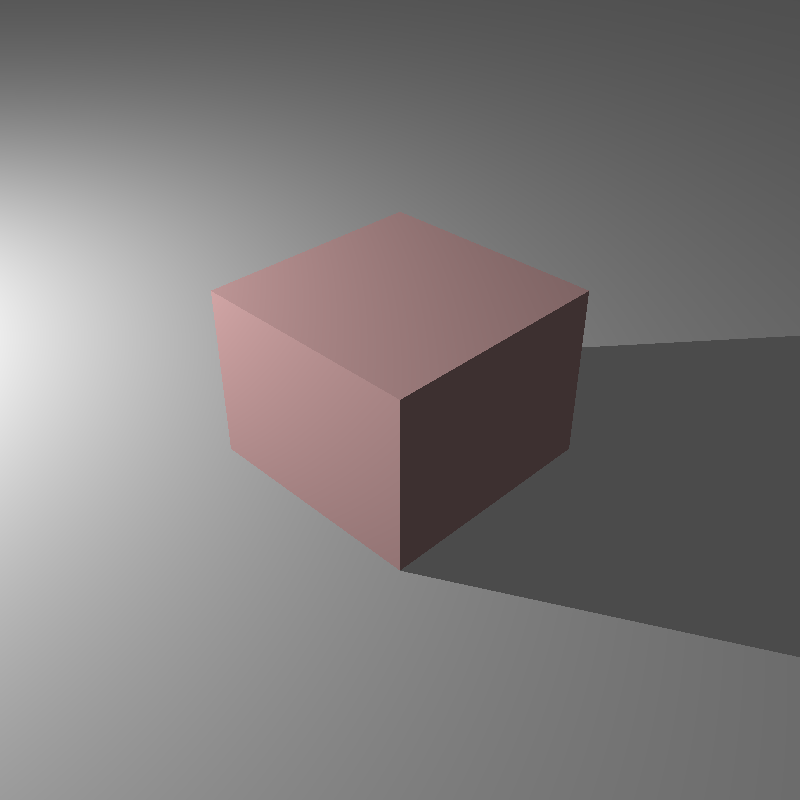
I could not find the reason but after a while, I saw something in the xml file. There is a thing called “degamma”. I did not pay attention to that at first. I understand that we have to modify reflection coefficients with that. I got the correct result after understanding that.
I also got gray cube because of an error in my code that I’ve missed(I was giving same value to each color channel, silly mistake)
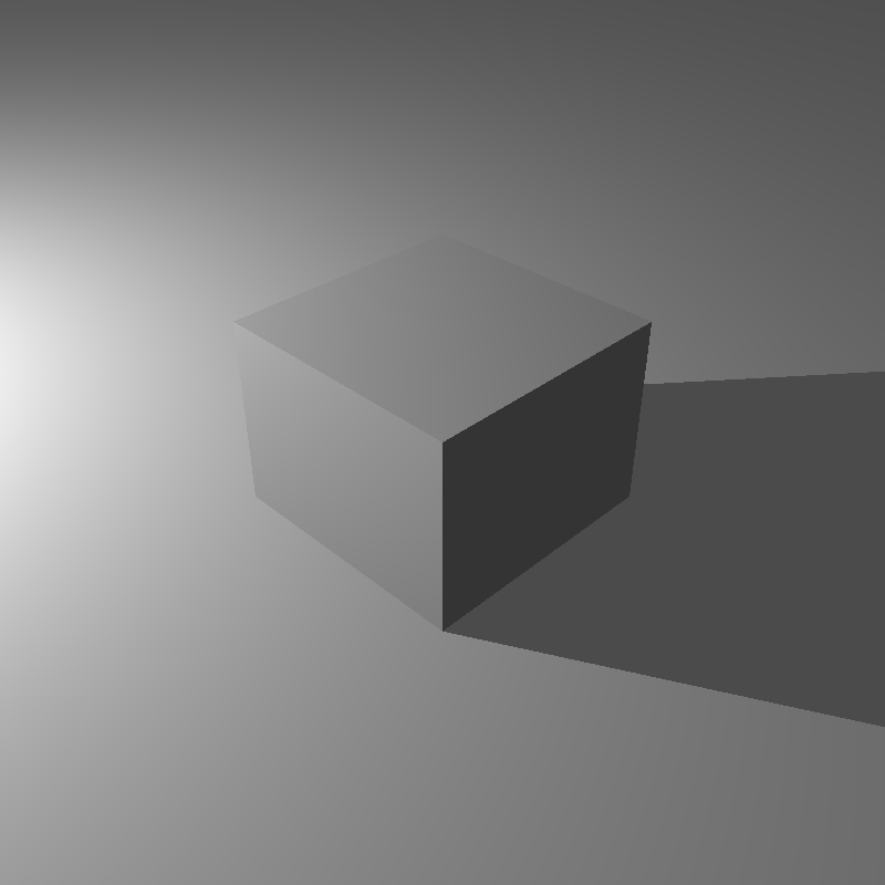
And lastly, there is the normal point light example given in homework files
Conclusion
This week, I tried to deal with hdr images, added exr support, implemented spot, environment and directional lights, refactored my code for future extensions and produced not exactly the same but similar results.
Fun Update
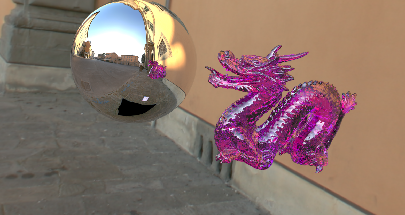
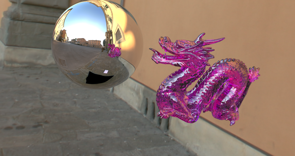
I had some free time this day and wanted to look at the blogs of previous years. I saw blog of one of our assistants in the department Kadir Cenk Alpay’s blog(much respect) and saw that he created a cool looking scene with environment light. There was a mirror sphere and a dielectric dragon. He also shared the xml file of that scene in the blog. I will render it and put it as the image of this homework because I liked it a lot(all credit goes to him :D)
I wanted to make sure that my raytracer can render the scene. First of all I had to make some changes in the xml file because some things were different. Here is the modified xml file.
I expected to see good results in first try but no :D. I had a black screen instead. After thinking a while, I saw that I did not implement environment map lights for rays that are exiting dielectric surfaces or being reflected from mirrors and are not hitting any objects.
So after I implemented this, I started getting results but not all the time. In some attempts, It was randomly giving blank screen. I guessed that it is because of the random vector selection or not initializing a value and compiler is giving it a junk value with optimization flags. The latter guess was correct so I found the variables that I did not initialize and the mistake was gone. This is the image 😀
But there is still a problem. It is about tone mapping and resolution/samples we use in the scene. I investigated this problem and saw that if luminances of pixels in the image come out really low, this creates a problem while taking log average and average value becomes nan. I solved this issue with multiplying each pixel with a factor if HDR imaging is enabled, but it did not completely solved this issue. Exr files come out just fine, but I cannot tonemap the images. I will find a better solution after my final this week.
Update: I have found the problem in tonemapping after hours of debugging. Log average becomes nan not because of luminances being low, It is because some very few ray tracing operations (like 1 and 2) may result in pixels carrying nan values. I searched for reasons and saw that there are different vertex data in xml file which are equal. I think it should not be like this. I have handled it in my xml parsing code. I have also handled ray tracing operation givin nan values by giving 0 value if that happens. It seems that it solved the problem. Since we also have a lot of samples, taking average does the job and I don’t see any artifacts. Since I have solved that problem too, I can sleep now. Raytracing is really addictive 😀

One thought on “RayTracing Revisited: Part 5”